GAIN
The gain of the OPA have to be choosed depending of the expected temperature range and the thermocouple type.Thermocouple tables can be found here : http://srdata.nist.gov/its90/main/
ex for K type :
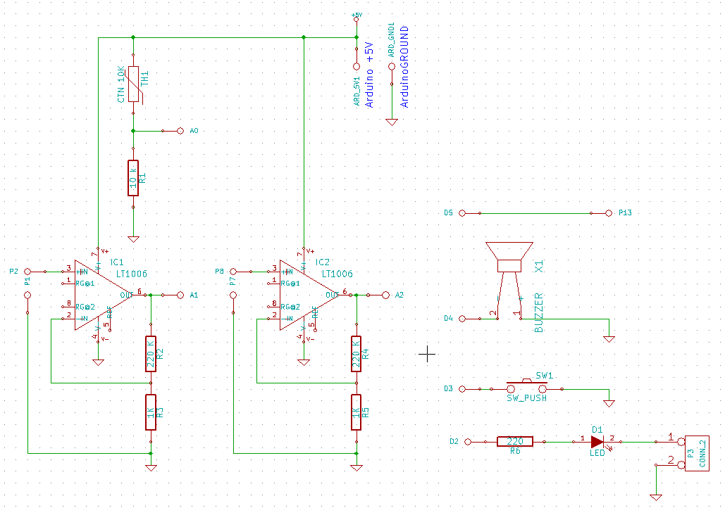
with gain = (220+1)/1 = 221.
Uth max = 5V / 221 = 22,6 mv
Max temperature range beetwen 500 and 600 °C . (approx 546 °C, according NIST table).
| Temp (°C) | Uth (mV) | Gain |
| 100 | 4.1 | 1220 |
| 200 | 8.14 | 614 |
| 300 | 12.21 | 409 |
| 400 | 16.4 | 304 |
| 500 | 20.22 | 242 |
| 600 | 24.9 | 200 |
| 700 | 29.13 | 171 |
Bill Of Material
A0 0,1' connector |
IC1 LT1006 |
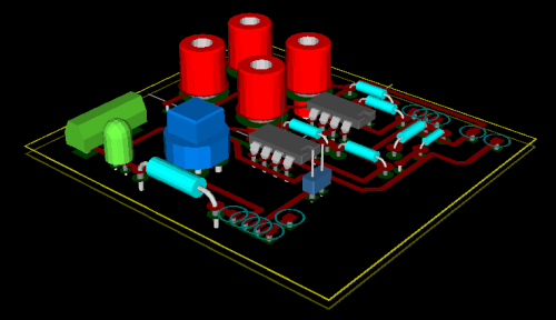
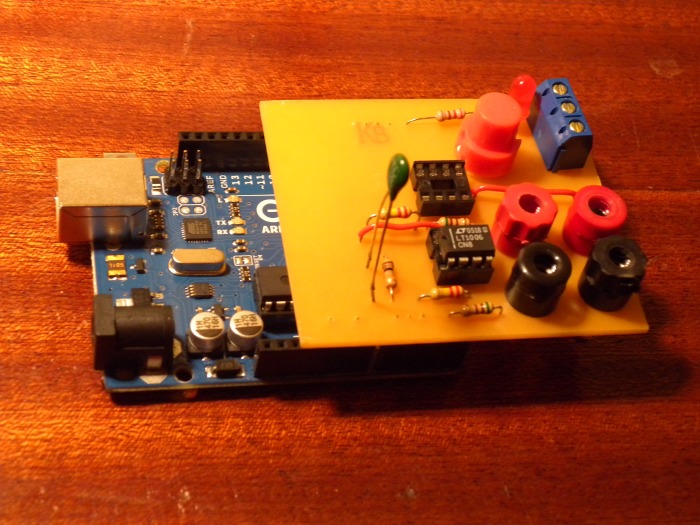
BOARD
The board is single face, with two strap wires.
The PDF for copper side
kicad files for board and schematic
IMPORTANT TIPS : DO NOT mount the TNC on the board before calibration. For calibration the best is to put the TNC in water with a reference thermometer. If it's on the board it wont be easy.
Instead you'd better to sold two wires from the TNC to the board, or mount it with his long legs.
After calibration you can mount the TNC on the board.
SOFTWARE
Software is minimum : Voltage from TNC and OPA are read and converted in temperature. Output is sent on serial port for reading on serial monitor.Use serial monitor of arduino or any equivalent to read or record outputs
The conversion is done with piecewise linear interpolation. The interpolation is calculated with two table : one for the TNC and one for the TC.
#define TEMP 1
#define CAN 0
#define N_CTN 4 // number of points in TNC calibration table
#define N_TC 12  // number of points in thermocouple calibration table
// Table calibration for THERMISTOR
float calib_CTN [N_CTN][2] = {
{340,15},
{395,19},
{405,20},
{470,30} // put here calibration points : first the value read on arduino ADC, second the value read on your reference thermoemter.
};
// Table calibration for THERMO COUPLE
float calib_TC  [N_TC][2] = {
{0,0}, // first point : at 0°C the TC give no voltage
{25,10},
{135,40},
{305,86},
{444, 125},
{580,160},
{616,170},
{655,180},
{709,195},
{734,201},
{841,231},
{888,261}
};

void setup() {
  // initialize serial communication at 9600 bits per second:

  Serial.begin(9600);
  pinMode(2,OUTPUT);
  pinMode(4,OUTPUT) ;
  pinMode(3,INPUT) ; digitalWrite(3, HIGH) ;
}

// the loop routine runs over and over again forever:
void loop() {
  // read the input on analog pin 0:
  int Can_comp = analogRead(A0);
  int Can_TC = analogRead(A1);
  float T_ctn = converti(Can_comp , calib_CTN, N_CTN);
  float T_Thcp = converti(Can_TC, calib_TC, N_TC) ;


  // print out the value you read:

  Serial.print("CTN ADC out ="); Serial.print(Can_comp);
  Serial.print("\tT ref ="); Serial.print(T_ctn);
  Serial.print("\tTcoup ADC out ="); Serial.print(Can_TC);
  Serial.print("\tTemp TC ="); Serial.print(T_Thcp);
  Serial.print("\t"); Serial.println(T_Thcp + T_ctn,2); // Temperature from Thermo couple is
                                                            // added to cold junction temperature for compensation

  delay(100);        // delay for stability
}

float Int_lin(float x,             // input : abcisse where the fonction is to be interpolated
              float X1, float Y1 , // Coordinates of lower interpolation point
              float X2, float Y2   // Coordinates of upper interpolation point
			  ){
  // linear interpolation : x beetween X1 and X2
  // return interpolated value of y = f(x)
  float a , b ;
  a = (Y1 - Y2) / (X1 - X2) ;
  b = Y1 - a*X1 ;
  return a*x + b ;
}

float converti(float X ,          // value read on ADC to convert in °C
               float calib[][2],  // Calibration table to use --> not the same for TCN en thermo couple
               int N
			   ){
	int i ;
	if (X < calib [0][CAN]){ // Entry outside calibration table (lower) --> extrapolation
	                         // with the two first points of table
		return Int_lin(X,
				calib [0][CAN], calib [0][TEMP] ,
				calib [1][CAN], calib [1][TEMP]) ;
	}
	if (X > calib [N-1][CAN]){ // Entry outside calibration table (higher) --> extrapolation
	                             // with the two last points of table

		return Int_lin(X,
				calib [N-1][CAN], calib [N-1][TEMP] ,
				calib [N][CAN], calib [N][TEMP]) ;
	}
	for (i=0 ; i < N ; i++){
		if (X < calib [i][CAN]){
			return Int_lin(X,
					calib [i-1][CAN], calib [i-1][TEMP] ,
					calib [i][CAN], calib [i][TEMP]) ;
		}
	}
}
CALIBRATION
As is, the software cant make mesure : The user had to calibrate is shield and to fill tables before.
tables here are just for exemple and works with my thermocouples, my NTC and the gain of my amplifiers. Components Tolerances doesn't allow you to use those tables as is .
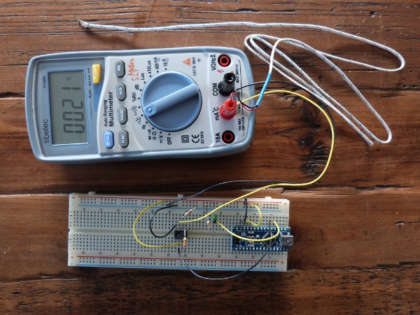
For calibration you need a multimeter with thermocouple fonction.
COLD JUNCTION / TNC
First you need to calibrate the cold junction compensation.Put the TNC in hot water (45°C as exemple) together with a reference thermometer. Read and note the output of TNC ADC (A0) in parallel with reading from your thermometer. Let the temperature fall and note ADC output and temperature every 10 degres. 10 degres is for exemple : the interpolation function dont need regular intervals. You can use mesure randomly spreaded in the mesure range.
Put the TNC in cold water (0 °C or 10 °C) and note together ADC output and thermometer. Let the temperature rise and note several reading.
Prepare the calibration table : intervals dont need to be regular but you need to order ADC reading from smallest to bigest.
Writte the table in the program upload it in the Arduino and check on the temperature range.
The software can make mesure outside of the range of the table : in those case mesurements are EXTRAPOLATED from the most extreme point of table.
THERMOCOUPLE
Mesure and note room temperaturePlug thermocouple to the shield AND to your multimeter or electronic thermometer : yes, plug the TC to the shield (P2 and P1) and IN PARALLEL on your electronic thermometer.
Of course you could use two thermocouples (on on the shield and one for the termometer), but it would be harder to be sure have the same temperature on both termocouple. Put the thermocouple in a hot area (owen) an rise temperature. Note ADC output from the Arduino and temperature from your thermometer.
Your thermometer has a built in cold junction compensation. So you need to minore the temperature of the the value of the room temperature.
Prepare the calibration table and upload the program.